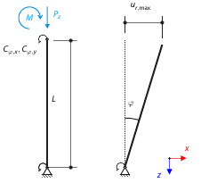
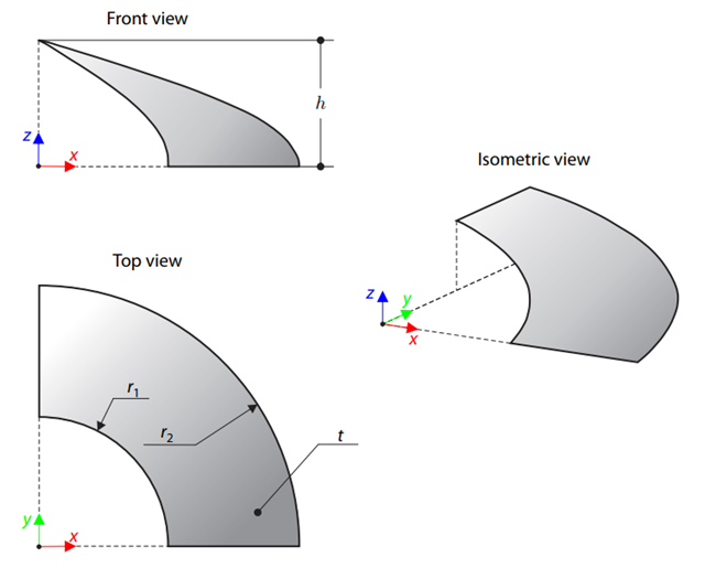
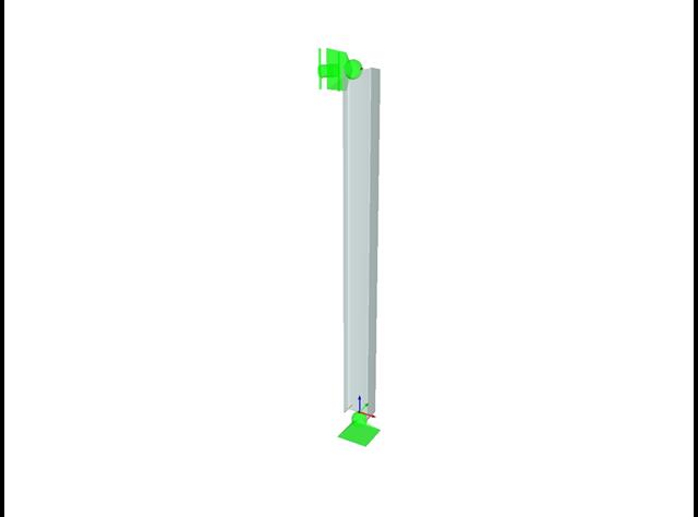
Consider a rigid scaffolding tube, fixed at the bottom using the Scaffolding Nodal Support and loaded by both a moment and a force. Calculate the maximum deflection with consideration of initial slippage.
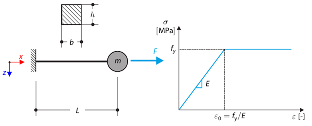
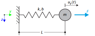
This verification example is based on Verification Example 0122. A single-mass system without damping is subjected to an axial loading force. An ideal elastic-plastic material with characteristics is assumed. Determine the time course of the end-point deflection, velocity, and acceleration.
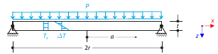
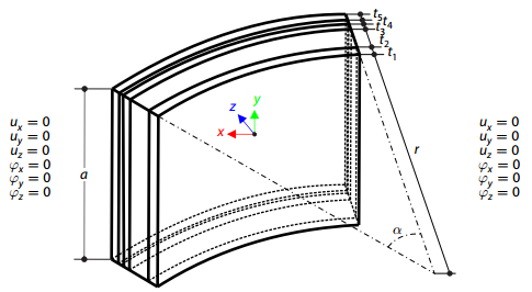
Determine the maximum deflection and maximum radial moment of a simply supported circular plate subjected to uniform pressure, uniform temperature, and differential temperature.
Consider a rigid scaffolding tube, fixed at the bottom using the Scaffolding Nodal Support and loaded by both a moment and a force. Calculate the maximum radial deflection by exceeding the capacity of the scaffolding support.
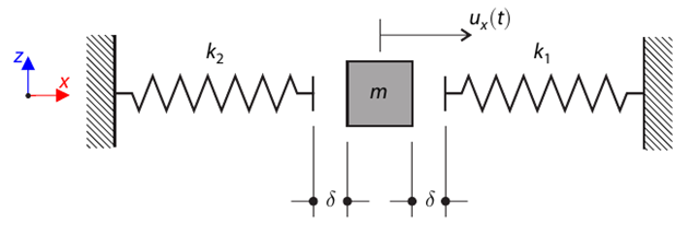
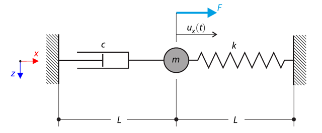
A single-mass system with clearance and two springs is initially deflected. Determine the natural oscillations of the system - deflection, velocity, and acceleration time course.
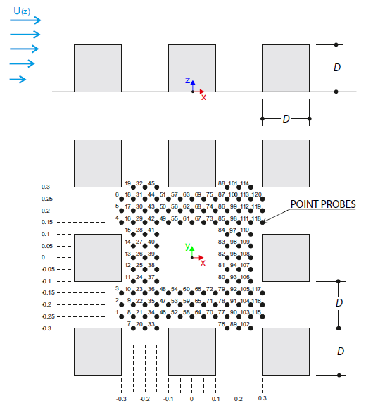
The verification example describes wind loads in several wind directions on a model of a group of buildings. The model consists of eight cubes. The velocity fields obtained by the RWIND simulation are compared with the measured values from the experiment. The experimental data are measured using a thermistor anemometer in the wind tunnel.
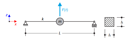
A long, thin beam is carrying a concentrated mass and is loaded by a time-dependent force. It is simply supported. The problem is described using the following parameters. Determine the deflections in the given test times.
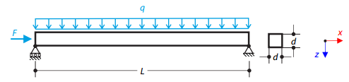
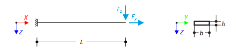
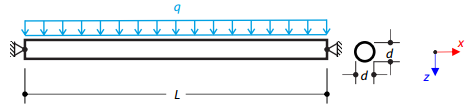
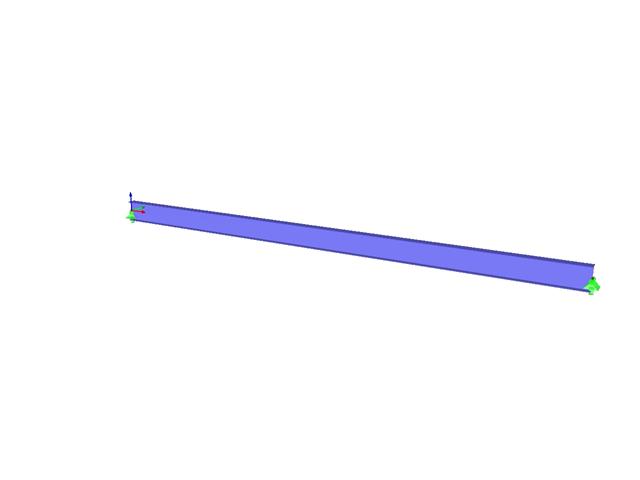
A steel beam with a square cross-section is loaded with an axial force and distributed loading. The image shows the calculation of the maximum bending deflection and critical load factor according to the second-order analysis.
One layered square orthotropic plate is fully fixed at its middle point and subjected to pressure. Compare the deflections of the plate corners to check the correctness of the transformation.
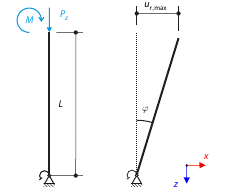
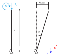
Consider a rigid scaffolding tube, fixed at the bottom using the Scaffolding Nodal Support and loaded by both a moment and a force. Self-weight is not considered. Considering an infinitely rigid beam, determine the maximum radial deflection.

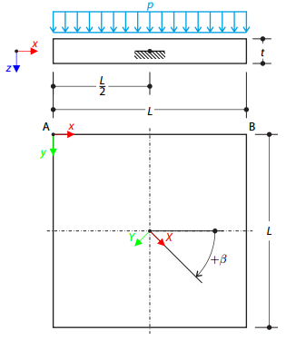
Consider an ASTM A992 W 18x50 beam forspan and uniform dead and live loads as shown in Figure 1. The member is limited to a maximum nominal depth of 18 inches. The live load deflection is limited to L/360. The beam is simply supported and continuously braced. Verify the available flexural strength of the selected beam, based on LRFD and ASD.
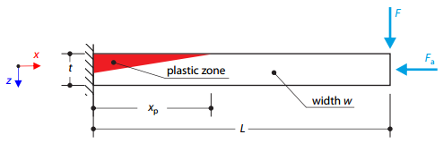
A cantilever is fully fixed on the left end and loaded by a transverse force and an axial force on the right end. The tensile strength is zero and the behavior in the compression remains elastic.
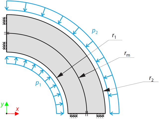
A two-layered, open-ended, thick-walled vessel is loaded by inner and outer pressure; therefore, there is no axial stress. While neglecting self‑weight, the radial deflection of the inner and outer radius, and the pressure (radial stress) in the middle radius is determined.
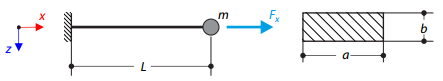
A cantilever of rectangular cross‑section has a mass at the end. Furthermore, it is loaded by an axial force. Calculate the natural frequency of the structure. Neglect the self‑weight of the cantilever and consider the influence of the axial force for the stiffness modification.
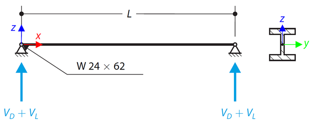
An ASTM A992 W 24×62 beam with end shears of 48.000 and 145.000 kips from the dead and live loads, respectively, is shown in Figure 1. Verify the available shear strength of the selected beam, based on LRFD and ASD.
A composite plate consisting of three glass layers, one foil layer, and an inner space with dry air, is fully fixed and loaded with a variable temperature. Neglecting its self-weight, determine the plate's maximum deflection.
Prove that coupling different dimensional elements does not affect the results. A cantilever with a rectangular cross-section is fixed at one end and loaded at the other by concentrated forces. Neglecting its self-weight and assuming only small deformations, determine the cantilever's maximum deflections.
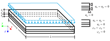
Determine the maximum deflection and stress in the z-direction of the composite plate, consisting of two glass layers and one foil layer in between, subjected to uniform pressure.
A steel cable or membrane with pins on both ends is loaded by distributed loading. Neglecting its self-weight, determine the maximum deflection of the structure using the large deformation analysis.
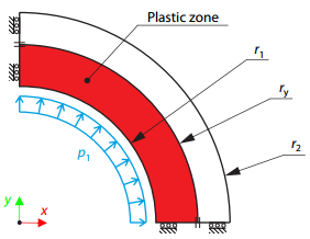
A thick-walled vessel is loaded by an inner pressure such that the vessel reaches an elastic-plastic state. While neglecting self‑weight, the analytical and numerical solutions for the radial position of the plastic zone border (under the Tresca hypothesis) are determined and compared.
A single mass system is subjected to loading force. Determine the deflection of the system.
Verify that a beam of different cross-sections made of Alloy 6061-T6 is adequate for the required load, in accordance with the 2020 Aluminum Design Manual.
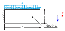
Determine the maximum deflections of the block while considering or neglecting shear effect. The square block of the isotropic material is fully fixed at one end and loaded with uniform vertical pressure.
A single-mass system with dashpot is subjected to a constant loading force. Determine the spring force, damping force, and inertial force at the given test time. In this verification example, the Kelvin--Voigt dashpot (namely, a spring and a damper element in serial connection) is decomposed into its purely viscous and purely elastic parts, in order to better evaluate the reaction forces.
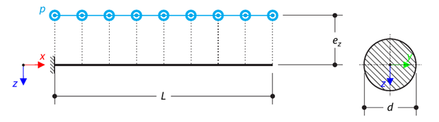
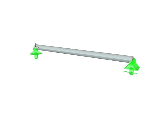
A console made of a round bar is loaded by an eccentric uniform load. Determine the maximum deflection and maximum twist of the console using the geometrically linear analysis.
Consider an ASTM A992 W 18×50 beam forspan and uniform dead and live loads as shown in Figure 1. The member is limited to a maximum nominal depth of 18 inches. The live load deflection is limited to L/360. The beam is simply supported and continuously braced. Verify the available flexural strength of the selected beam, based on LRFD and ASD.
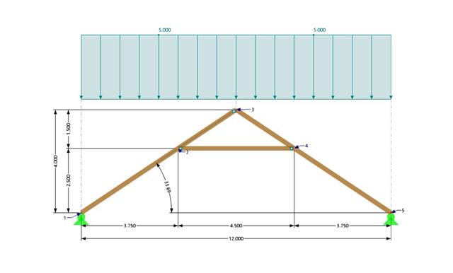
A collar beam roof with the selected geometry is compared in terms of its internal forces between the calculation using RFEM 6 and the manual calculation. In total, three load systems are analyzed.
A membrane is stretched by means of isotropic prestress between two radii of two concentric cylinders not lying in a plane parallel to the vertical axis. Find the final minimum shape of the membrane - the helicoid - and determine the surface area of the resulting membrane. The add-on module RF-FORM-FINDING is used for this purpose. Elastic deformations are neglected both in RF-FORM-FINDING and in the analytical solution; self-weight is also neglected in this example.
Determine the allowable axial compressive strength of a pinned 8-foot-long beam of various cross-sections made of Alloy 6061-T6 and laterally restrained to prevent buckling about its weak axis in accordance with the 2020 Aluminum Design Manual.
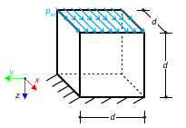
Determine the maximum deflection of a cube. The cube's lower side is fully fixed and the upper side is subjected to shear loading.